Coaxial Harmonic Absorptive Filters
- Series: C70-A Series
- Category: FIlters
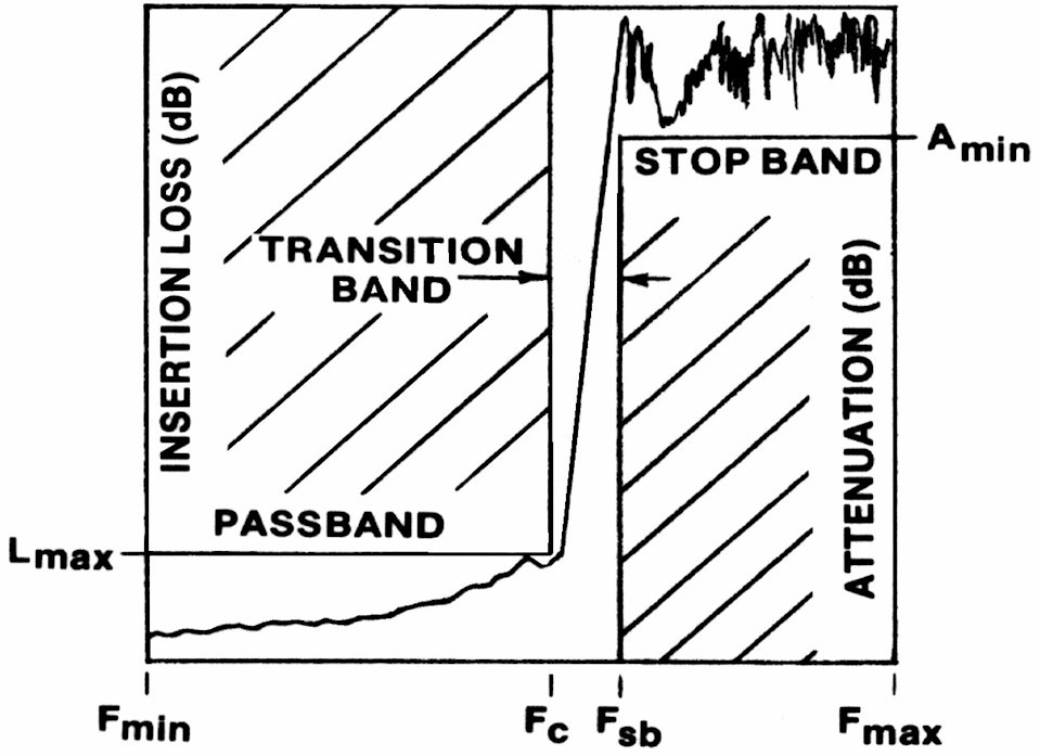
M.E.C.’s C70-A Series of coaxial harmonic absorption filters have a low pass characteristic distinguished by an ultra sharp cutoff skirt ranging from under 1dB passband loss to as high as 90dB attenuation in a transition band no wider than 10% of Fc. Their pass-band extends from DC to the specified Fc in the 2.0 – 18.0 GHz range and the stop band from Fc +. 1 Fc to over 3 Fc.
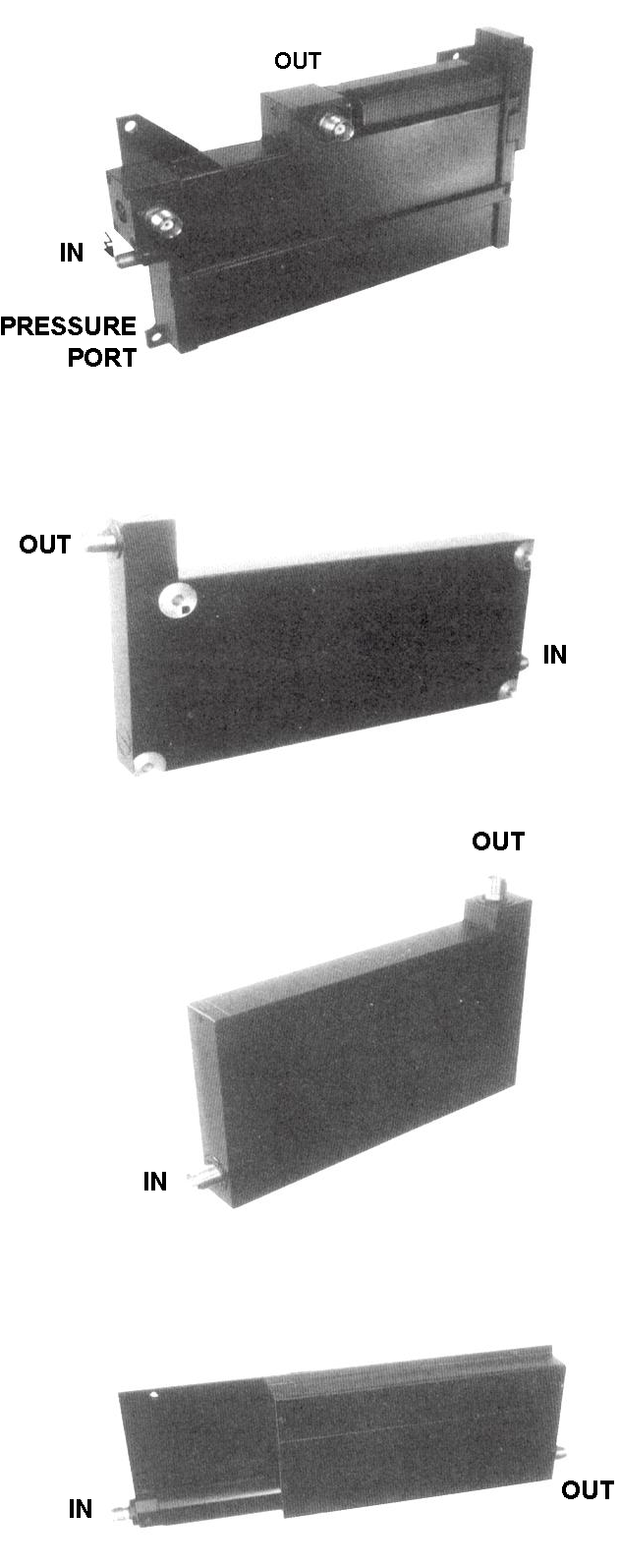
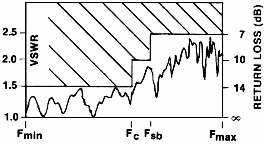
Unlike the more common C70-L Series, these C70-A filters do not reflect harmonic energy back to the transmitter but absorb it internally while maintaining low input VSWR over transition and stop bands. This feature makes them indispensable in today’s ECM systems to condition signals and protect TWT’s from harmonics and other harmful reflections which would otherwise cause overheating, premature burnout, higher EMI, and greater detection vulnerability
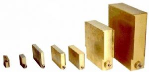
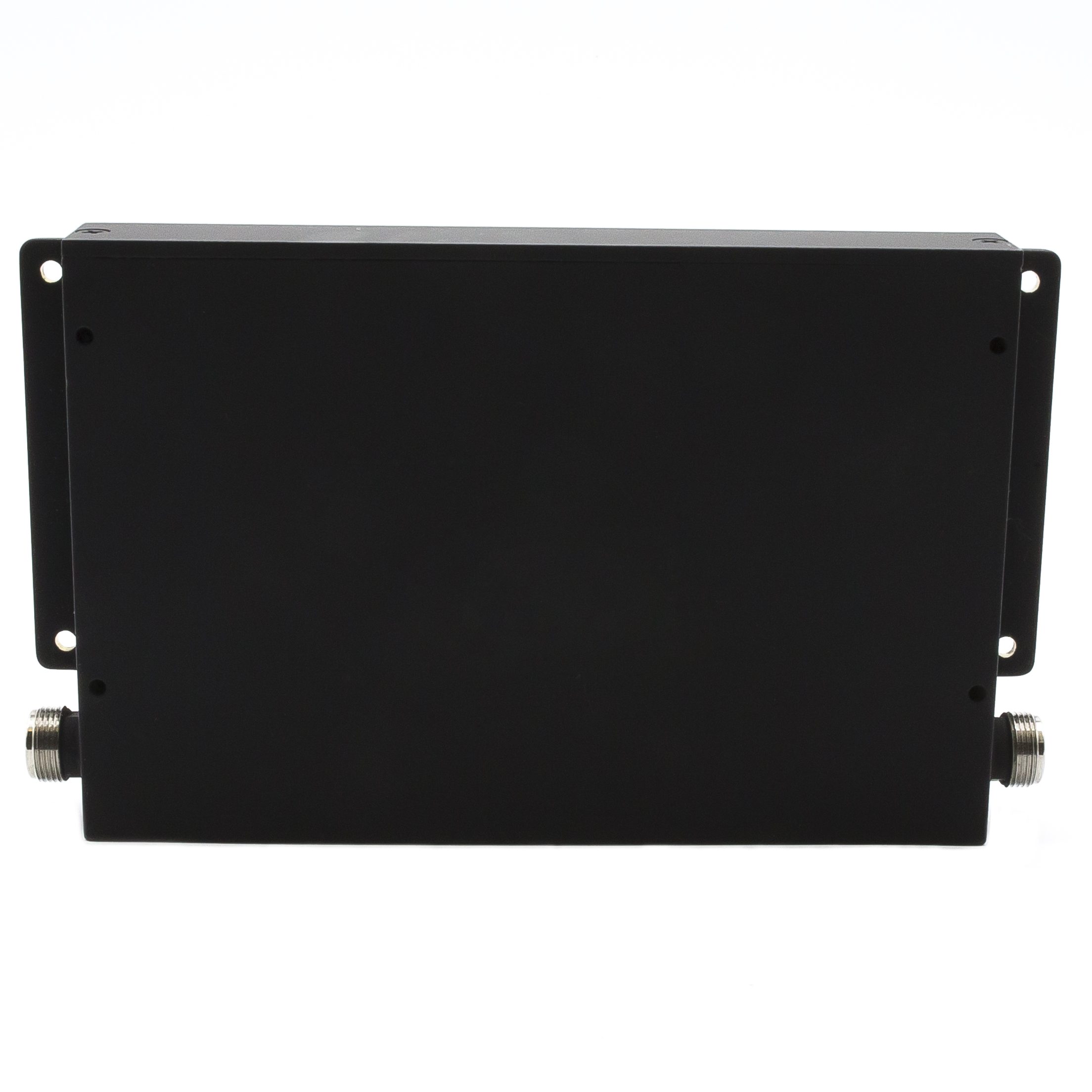
Other notable features include low passband loss from 0.3 to 1 dB; VSWR under 1.5:1; compact size typically 5” x 7” x 1” and weight under 2 pounds for a cutoff in X-band. Power handling over pass and stop bands is in the hundreds of watts CW, and several kilowatts peak, under non-conditioned temperature/altitude and vibration environments of MIL-E-5400. Exact figures depend on the frequencies, attenuation and connectors required.
The body is made of aluminum plates with rugged dip-brazed construction. Internal absorbers, connectors and all other materials are especially selected to withstand prolonged high temperature operation without external cooling or thermal mounting. Finish is chromate conversion per MIL-C-5541, Class 3, with high emissivity black epoxy enamel paint.
- Low Reflection Stop Band
- Ultra Sharp Cutoff
- Up to 90 dB Attenuation
- High Power
- Low Loss
Specifications
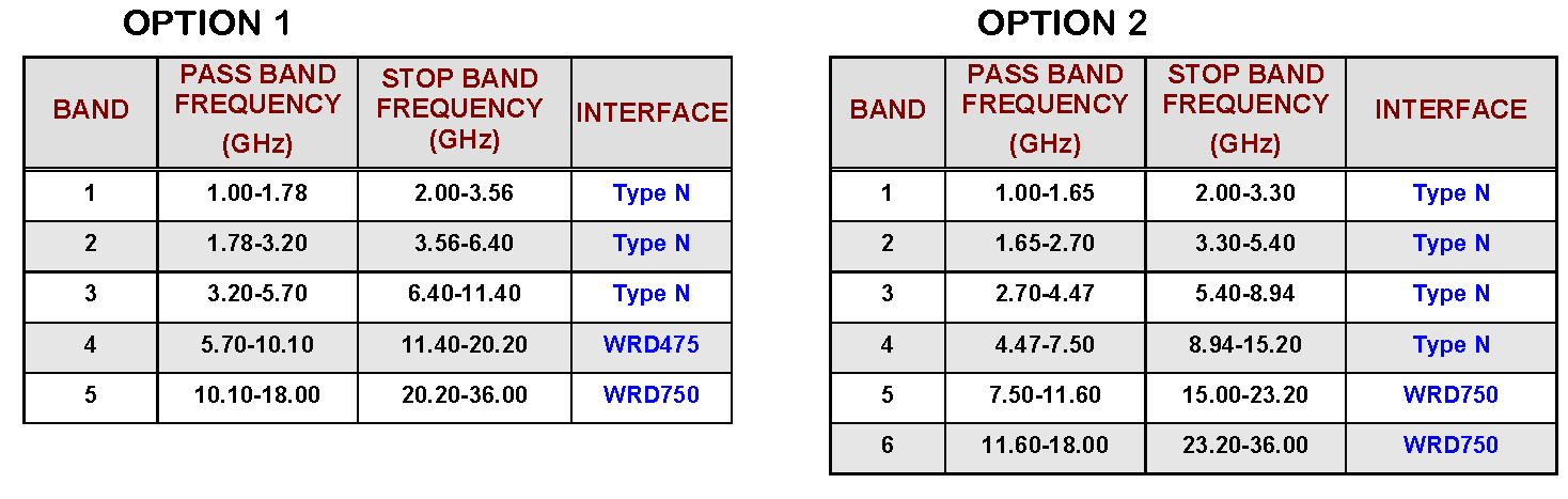
Suggested Model Groupings: M.E.C. offers a complete line of harmonic absorptive filters covering full TWTA bands of either 1.0 – 18.0 GHz or 2.0 – 18.0 GHz. Refer to the tables below for suggested model groupings to cover these bands. The lower part of the band utilizes coaxial models (C70A Series) while the upper part of the band utilizes waveguide (Rectangular = 70A Series / Double-Ridge = R70A Series).
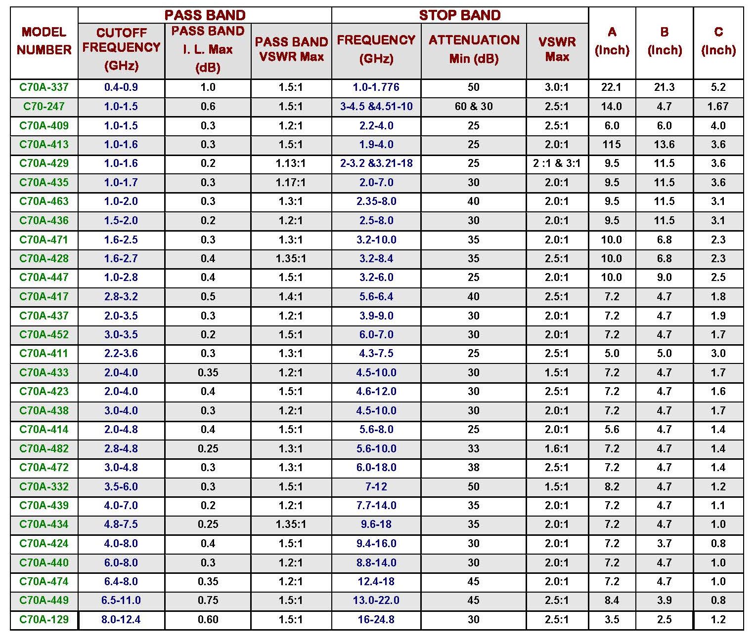
Common Models: The table below is a representative sample of M.E.C.’s available designs. Contact M.E.C. with your specific requirements. Our engineering staff will be glad to discuss your needs.

Order and Sales Information
(1) Choose from the models listed above or specify Fmin, Fc, Fsb, Fmax, Lmax (insertion loss). Amin (attenuation), power (CW & Peak), connectors (TNC, N, SC, MLT, LC, EIA series), and any other requirements.
(2) Size and configuration are determined by the above specifications and may be tailored to suit customer preferences.
TYPICAL DATA