Custom Designed Power Dividers for Antenna Phased Arrays
- Category: Combiners, Dividers, & Hybrids
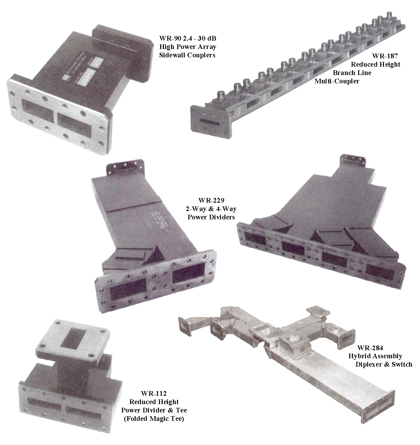
Power dividers with precise amplitude and phase control are available in waveguide, coaxial, and slab line configurations tailor-made to the customer’s requirements. A wide range of power dividing components are utilized to achieve best over-all performance. Typical TEM mode devices selected include quadrature couplers, split-tee dividers, and rat race rings; waveguide devices include cross guide, sidewall, broadwall, and branch line couplers, as well as magic tee hybrids.
M.E.C.’s for handling special designs and requirements of the customer are enhanced by extensive experience in moderate and high power networks, in-house design, manufacture, and testing flexibility, computer-aided design of components and simulation of over-all performance, advanced machining capabilities for accurate reproducibility, and tight tolerance control. These assets coupled with power divider and antenna expertise enable M.E.C. to offer integrated sub-assemblies for specialized customer requirements. The principal advantage is that performance can be optimized to the application and interaction between discrete circuits can be eliminated. Other advantages include size and weight reduction.
Some of these dividers are described below. Each of these dividers have been developed for a specific application and serve to illustrate M.E.C.’s versatile capability.
32-Elements Monopulse Feed Network
This feed network is a dual 32:1 equi-phase L-Band power divider. It has two isolated coaxial inputs: a sum port (S), and a difference port (D). A 50 dB S sampling port is also provided. The illumination distribution at the output ports for both inputs is shown. The power divider is used as the feed network for an electronically scanned monopulse radar utilizing a Displaced Phase Center Antenna. Major characteristics of this experimental system are side lobes at –30 dB and low detection threshold.
Achieving the required power divider performance depended critically on an accurate power distribution and phase equality. The goals set to attain the desired characteristics were amplitude ± 0.2 dB, phase ± 1°, and insertion loss under 1 dB over the frequency range. A unique low loss and ultra stable transmission medium was used. Power handling is over 400 W CW and 5 KW peak. All specifications were exceeded; in particular, insertion loss was 0.6 dB.
6-ELEMENT L-BAND LINEAR ANTENNA ARRAY WITH INTEGRAL POWER DIVIDER
 Designed for use in an L-Band phased array antenna system, this is a 6:1 power divider and radiating module in a compact package. It consists of an SMA coaxial input, the dividing network, and 6 L-Band waveguide apertures as the radiating elements, sealed by dielectric pressure windows.
- PHASE EQUALITY ±1°
- UNIT-TO-UNIT PHASE TRACKING < ± 0.5°
- POWER DISTRIBUTION± 0.25 dB AT 6 PORTS
- INSERTION LOSS 0.23 dB TYP.
- APERTURE ISOLATION > 20 dB.
- INPUT VSWR <04
- BANDWIDTH 5% TYP.
Operationally, the complete antenna consists of a horizontal array of 32 such 6- elements modules. This produces a 6 x 32 array for scanning in the horizontal plane. Each 6-element module is fed from the appropriate port of the 32-way monopulse divider (described on the previous page) through a phase shifter for scanning. This 192-element advanced monopluse Displaced Phase Center Antenna is shown during flight test.
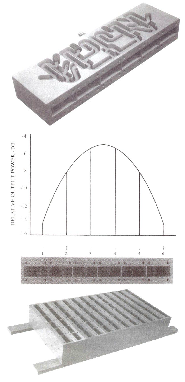
120-ELEMENT FEED SUB-ASSEMBLY FOR DOME RADAR ANTENNA
 APPLICATION · The reduced-height waveguide sub-assembly (Figures A1 & A2) is part of the power divider network for a multi-element airborne hemispherical coverage X-Band phased array radar. Output ports totaling 2,500 for the complete assembly are distributed to fill a circle approximately 40” in diameter (Fig. B). The power dividers are grouped into discrete sub-assemblies of four rows each. The 40” disc surface is formed by stacking these linear sets of differing lengths, thus approximating the desired feed aperture. Following is a description of the central sub-assembly; it contains the most elements and is representative of all others.
FEED DESIGN · This power divider contains 120 output ports and 8 input ports. Each row or level (four shown in Fig. D) contains two separate primary wave-guides externally fed. The structure is bilaterally symmetric and a liquid cooling channel runs the full length of the row at each level. In each primary waveguide (Fig. E) 15 sets of coupling apertures are machined. The output power profile (Fig. C) is roughly an exponential taper peaking in the center.
Fifteen secondary waveguides (Fig. F) lie beneath each primary guide, sharing with it a common broadwall .030” thick. In addition, each secondary has a two-section impedance transformer leading to a phase trimmer output mounting hole.
The four levels are staggered relative to each other by a distance of .630” or half the element-to-element spacing thus producing a 30 x 4 checker-board pattern to constitute the diameter of the round aperture. Weight being a prime concern, extensive lightening cuts were made at each stage. The complete sub-assembly measured 38.7” x 5.6” x 1.45” and weighed 5 lbs.
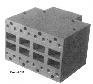
8-WAY HIGH POWER WAVEGUIDE DIVIDERS
These computer-manufactured low loss dividers were designed for X and Ku-Band phased array antenna systems. Each consists of a single waveguide input feeding 8 waveguide outputs through a dividing network. Internal circuitry provides all outputs with equal amplitude and phase distribution.
- AMPLITUDE BALANCE ± 0.2 dB.
- PHASE BALANCE ± 2°
- INSERTION LOSS 0.35 dB TYP.
- ISOLATION BETWEEN OUTPUT PORTS 15 dB MIN.
- INPUT VSWR 1.2:1 TYP.
- POWER 800 W CW MIN.
- BANDWIDTH 20% TYP.
- X-BAND 2.95” x 4.57” x 4.33”
- Ku-BAND 1.60” x 2.68” x 2.56”
6-ELEMENT C-BAND LINEAR ANTENNA ARRAY WITH INTEGRAL POWER DIVIDER
 Developed at a higher frequency for the same application as the L-band array, this 6:1 power divider and radiating module machined from a single aluminum block forms a still smaller, more compact unit. Dimensions are 1.05” x 1.96” x 6.80”.
- 3 mm INPUT WAVEGUIDE OUTPUTS
- POWER DISTRIBUTION ± 0.2 dB AT 6 PORTS
- INSERTION LOSS 0.3 dB TYP.
- PHASE EQUALITY ± 0.2°
- UNIT-TO-UNIT PHASE TRACKING ± 0.3°
- APERTURE ISOLATION > 18 dB
- BANDWIDTH 5% TYP.
- 6 x 12 ARRAY FOR SCANNING
MORE DIVIDERS
Order and Sales Information
(1) Please contact M.E.C. with your specific requirements. All customer designs are welcome.