Double-Ridge Broadwall Directional Couplers
- Series: R160 Series / R160A Series / R200 Series
- Category: Couplers
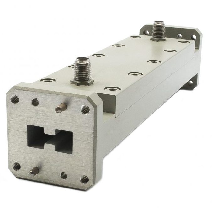
 M.E.C.’s broadwall directional couplers consist of double-ridge primary and secondary waveguide sharing a common broadwall where multi-hole arrays provide the required coupling level in the forward direction relative to the input wave and high directivity in the reverse direction.
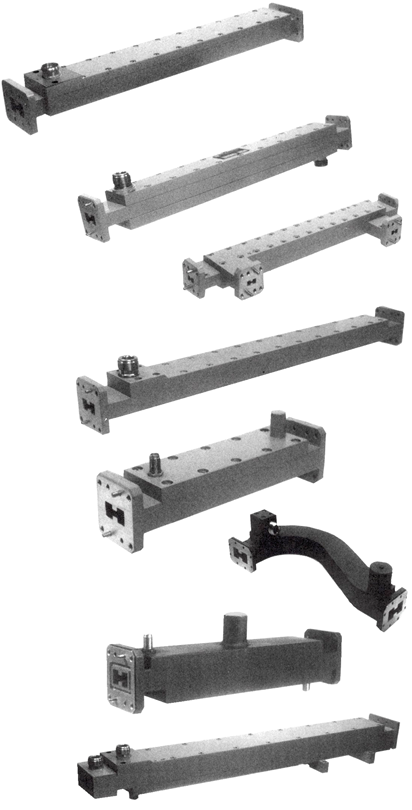
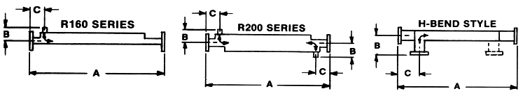
For the basic R160 series, primary waveguide is flanged at both ends with excellent VSWR and loss characteristics while the secondary waveguide has a precision internal termination at its isolated end along with a well-matched coaxial output at the coupled port suitable for attaching a video crystal detector or power monitor. In the H-bend style, a flange output is provided in place of the connector for applications requiring a waveguide coupled port.
The dual R200 series has two coupled secondaries to independently monitor both the forward and reverse waves with the same or different coupling level on each side.
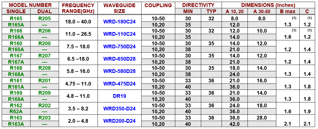
Broadwall couplers are capable of superior directivity due to the large number of coupling holes which can be used. As such, they are the heart of any reflectometer test stand measuring the reflection of double-ridge components. Given the importance of directivity, M.E.C. offers two options: the standard R160 & R200 with minimum directivity of 30 dB adequate for most laboratory measurements of VSWR down to about 1.12:1 and the R160A series with minimum directivity of 38 dB to measure VSWR levels as low as 1.04:1 or to perform measurements requiring high precision (i.e. lab use or calibration purposes).
Other available options include units with coupling levels as tight as 3 dB and as loose as 80dB, high power for peak and CW transmitter stands, various mechanical configurations, compact dimensions, pressure sealing, and a large assortment of waveguide flanges and coaxial connectors.
While most couplers of this type are made of waveguide extrusions and discrete flanges which are joined together by dip-brazing, M.E.C.’s couplers are fabricated as an integral unit to minimize the number of leaky seams, improve dimensional control, preserve surface finish, and prevent internal distortions. The result is a sturdy unit with superior electrical performance well suited for many years of rough service on the bench or in the field.
Flanges are cover type with alternate tapped and clearance holes. Coaxial connectors are passivated stainless steel and are solidly anchored into the body. Finish is chromate conversion per MIL-C-5541, Class 3 and paint is gray epoxy enamel
- High or Extra-High Directivity
- Built to Last
Specifications
- Coupling: 10, 20, 30, 40, 50 dB
- Mainline VSWR: 1.06 max.
- Secondary VSWR: 1.35:1 max., coaxial / 1.2:1 max., waveguide
- Frequency Sensitivity: ± 1.0 dB max. (octave band)
- Coupling Mean: ±0.8 dB
Notes:
- (1) 11.0 – 26.5 GHz & 18.0 – 40.0 GHz couplers have H-bend style secondaries.
- (2) For dual 10 dB couplers, two single couplers are used back to back resulting in a length of 2A.
Order and Sales Information
(1) Specify frequency limits if less than full band to obtain further optimization or specifications.
(2) Order by model number and add coupling level suffix as follows:
- “-10” for 10 dB
- “-20” for 20 dB
- “-30” for 30 dB
- “-40” for 40 dB
- “-50” for 50 dB
(3) Specify suffix for secondary coaxial connector for all models (except 11.0 – 26.5 GHz and 18.0 – 40.0 GHz) as follows:
- “-3” for SMA Female
- “-T” for TNC Female
- “-N” for type N Female
- “-7” for precision 7 mm
(4) H-Bend and other styles are available upon request.
(5) Please contact M.E.C. with your specific requirements. All customer designs are welcome.